5.3 Gouraud shading table
* VRAM is up to 7FFFFH. Do not define a Gouraud shading table beyond address 80000H.
The table defines RGB data in the order of vertex (A), (B), (C), (D). For lines, only vertices A and B are valid and correspond to the start and end points of the line. For sprites, vertices (A), (B), (C), and (D) correspond to upper left, upper right, lower right, and lower left.
This table is referenced from the command table when Gouraud shading is specified.
Table 5.2 Guro shading table
table address | corresponding vertex | |
Sprite, Polygon, Polyline | Line | |
Table start address | Vertex (A) | Line start point |
Table start address + 2 | Vertex (B) | line End point |
Table start address + 4 | Vertex (C) | Ignore |
Table start address + 6 | Vertex (D) | Ignore |
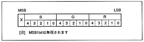
Figure 5.4 RGB code format
¡Color is not guaranteed if Gouraud shading is specified for the color code of the color bank code.