■File command
| command name | function |
|---|---|
| New (Ctrl+N) | Creating new model data |
| Open (Ctrl+O) | Loading existing model data |
| keep | Saving model data (*.pof) |
| Save as | Saving in *.MDL, *.ATA, *.MDB format (*1) |
| Add another window (Ctrl+W) | Add another viewpoint window |
| Grid resizing | Change the size of the square where model data is placed |
| Exit (Ctrl+Q) | Terminating 3DME.EXE |
■Edit command
| command name | function |
|---|---|
| Cancel (Ctrl+U) | Redoing the last work done (UNDO) |
| cut out | Delete selected model |
| copy | Copy selected model |
| pasting | Paste the model specified by "Cut" or "Copy" |
| Add polygon | Adding square polygons |
| Add BOX | Adding a cube |
| Add hexagonal prism | Add hexagonal prism (composed of quadrilateral polygons) |
| Added octagonal prism | Added octagonal prism (composed of quadrilateral polygons) |
| Add 4-point specified polygon | Create a polygon consisting of 4 arbitrarily selected vertices |
| Vertex movement | Move selected vertices (multiple selections possible) |
| cleanup | Delete multiple polygons on the same plane |
| Vertex cleanup | Unification of vertices at the same coordinates |
| Vertex cleanup settings | Setting how many dots to clean up nearby vertices |
| Vertex cross (0-1-2-3) | Used when a twisted polygon is created by specifying 4 points. |
| Vertex cross (0-2-1-3) | Used when a twisted polygon is created by specifying 4 points. |
| Automatic group division | Calculate which models exist in each grid (*2) |
| properties | Set the scale, swap the Y and Z coordinates in 3D space, rotate the left and right axes, and set the SG3 to be read at 64x (same as the "Properties" menu that appears when you click the right mouse button) |
■Selection command
| command name | function |
|---|---|
| Deselect | Deselect selected models |
| Invert selection | Swap selected and unselected models |
| PP | Copy and paste selected vertices. Then move, rotate, etc. |
| merge | Combine selected vertices into one |
| Edit parts | Selecting this command will open a new window where you can save the pre-selected parts as independent Pof data. When using the same data multiple times, you can save the data by editing this part, then recall it and copy and paste. Note that to change the viewpoint in this window, use the rotation command for Perspective. |
■Window command
| command name | function |
|---|---|
| attribute | Set properties of selected polygons |
| Group edit | Selected polygon |
| texture list | Open the list of textures used for model data |
| Display overlapping | Layer each window |
| Display vertically | Display each window vertically |
| close all | Close all windows |
| Window back color specification | Set window background color |
■Help command
| command name | function |
|---|---|
| version | Show version of 3DME.EXE |
■Commands such as viewpoint conversion
| command name | function |
|---|---|
| restore to original size | Restore window to original size |
| move | move window |
| resize | Resize the window |
| minimize | minimize window |
| maximize | maximize window |
| close | Close window |
| TexCheck | Display the model with the texture pasted |
| SelectCheck | Display selected part with texture |
| Front | View from the front of the map |
| Top | View from above the map |
| Right | View from the right side of the map |
| PersPective | View the map from various angles |
| PesPective2 | Color the polygons appropriately and view them from a PersPective perspective |
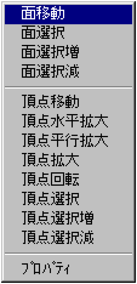
■Commands that appear when you click the right mouse button

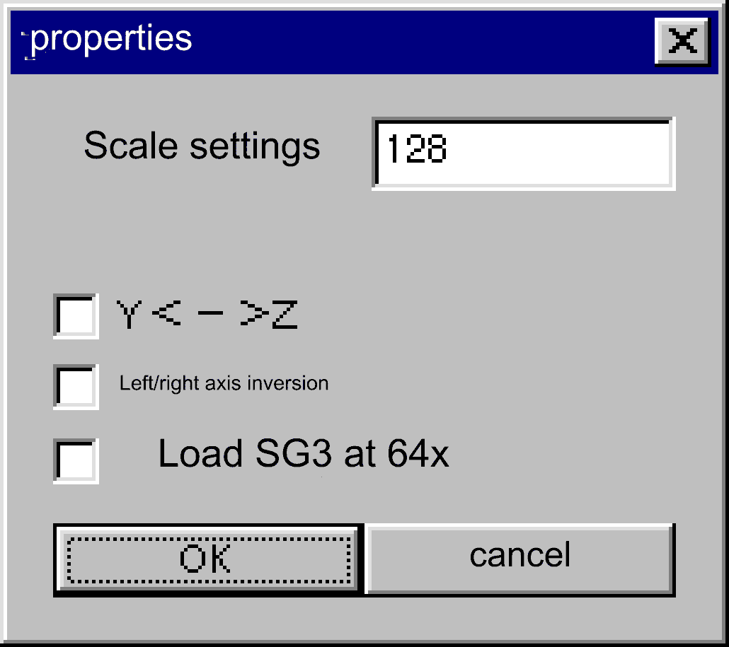
■Command that appears when you select "Properties" from the menu

| command name | function |
|---|---|
| Scale settings | Change the setting of the size of one square (unit: dot) |
| Y< −> Z | Swap the Y and Z coordinates in 3D space |
| left/right axis rotation | By checking, the upper right will be (0,0) |
| Load SG3 at 64x | *.Read SG3 data at 64x scale (When reading SG3, use the same reading method as Ver1.00) |
 ★ Graphic Tools Guide ★ 3DME User's Manual